
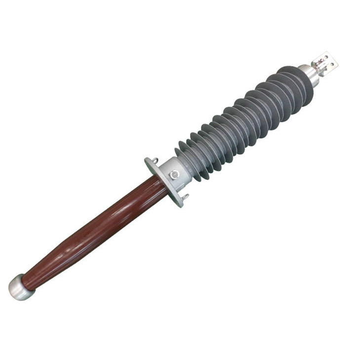

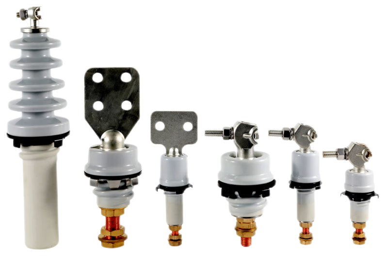
Draw-lead and solid-rod transformer bushings differ mainly in how the current-carrying conductor passes through the bushing and connects to the transformer winding. In a draw-lead arrangement, a separate winding lead is pulled through the bushing's central tube and terminated at the top. In a solid-rod arrangement, a rigid conductor forms part of the bushing assembly and is connected to the winding lead at the lower end. Neither connection method is automatically better: the choice depends on the existing transformer lead, continuous current, terminal geometry, installation sequence, and the bushing design.
How Each Bushing Carries Current
In a typical draw-lead configuration, the transformer winding lead travels upward through a hollow central tube. An installer pulls that lead through the bushing and secures it to the upper terminal. The current path therefore includes the separate draw lead and its top termination. The lead's size, insulation, routing, and connection method must match the application.
“Draw lead” does not always mean a flexible cable. An IEEE working-group guideline discusses both flexible copper cables and solid copper rods in draw-lead applications. The defining question is whether a separate conductor is drawn through the bushing, rather than whether that conductor can bend.
In the solid-rod arrangement discussed here, the bushing has a built-in rigid current-carrying stem. Its lower end connects to the transformer winding lead inside the tank, while the upper end provides the external terminal connection. The winding lead does not need to be pulled through the bushing's central tube. Exact connector and stem details vary by model, so the assembly drawing should govern the installation.
These are connection arrangements, not insulation technologies. A product description may separately identify the main insulation as OIP, RIP, or another specified design. NJREC's overview of high-voltage transformer bushing types provides context for those broader categories.
Solid-Rod and Draw-Rod Are Different Terms
Draw-rod, solid-rod, solid-stem, and bottom-connected are sometimes used loosely in product discussions. They should not be treated as interchangeable names on a purchase order. A draw-rod assembly can use a removable rod and a different current path from a bushing with an integral, current-carrying solid stem. Even the words “solid rod” need context: a solid copper rod can also be used as the separate conductor in a draw-lead application.
The IEEE C57.19.100 guide addresses the application of power apparatus bushings, but a project still needs its own manufacturer's cross-section and connection drawing. Specify which component carries current, whether that component is supplied with the bushing, and where the winding lead is joined. This avoids selecting a mechanically compatible-looking bushing with the wrong connection arrangement.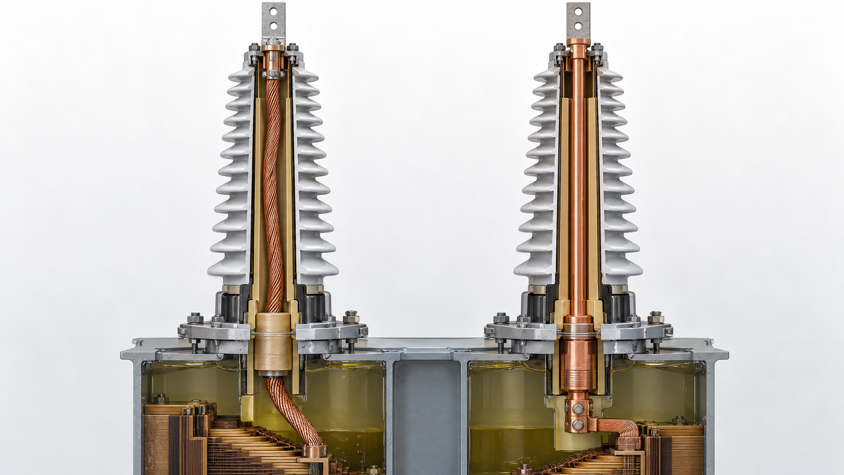
Draw-Lead vs Solid-Rod: Key Differences
| Selection point | Draw-lead arrangement | Solid-rod arrangement |
|---|---|---|
| Current path through the bushing | A separate lead or rod drawn through the central tube | The bushing's built-in rigid conductor |
| Oil-side connection | The separate conductor originates at, or connects to, the transformer winding lead | The winding lead joins the lower bushing terminal or stem |
| Upper connection | Draw lead terminates at the specified top connector | Built-in conductor terminates at the specified top terminal |
| Current-rating review | Check the bushing rating and the separate conductor's thermal suitability | Check the complete bushing rating and both terminal joints |
| Installation review | Confirm lead length, pulling access, top termination, and sealing sequence | Confirm access to the lower joint, fit, tightening method, and sealing sequence |
The table describes common arrangements, not universal product specifications. Confirm the actual current path and installation procedure on the drawing for the bushing being supplied.
For a draw-lead design, the bushing nameplate alone does not settle the current question. The separate lead's cross-section, material, insulation, temperature limit, bushing length, and oil conditions can affect its thermal capability. The transformer manufacturer and bushing supplier should confirm the complete assembly for rated service and any required overload duty.
How to Specify a Bushing for a New or Existing Transformer
Start with the transformer's connection drawing. Identify whether its winding lead is intended to pass through a hollow bushing or terminate at a lower bushing connector. For a replacement, record the arrangement actually installed; a matching flange or voltage class does not prove that the internal connections match.
Next, check the electrical duty: system voltage, insulation level, continuous current, and the project's specified test requirements. For a draw-lead design, also verify the conductor size and insulation and who supplies the lead. For a solid-rod design, check the stem and both connections as a rated assembly. Do not assume that a higher printed bushing current rating automatically increases the current capability of an existing winding lead.
Then compare the mechanical interfaces. Review the mounting flange, oil-end length and clearance, terminal dimensions, conductor reach, and access for the lower connection. Installation steps matter as much as the outline dimensions: one design requires the lead to be drawn and terminated at the top, while the other requires a secure bottom joint. Verify gaskets, sealing surfaces, orientation, and the required sequence against the supplier's instructions.
When requesting a quotation or checking a replacement, provide the existing bushing drawing and transformer connection drawing along with electrical ratings, terminal details, and installation constraints. Review NJREC's transformer bushing product range and submit the project requirements so the proposed connection can be checked against the equipment.
Final Takeaway
Choose between draw-lead and solid-rod transformer bushings by tracing the actual conductor from the winding to the external terminal. A draw-lead design uses a separately installed conductor through the bushing; the solid-rod arrangement described here uses the bushing's built-in rigid conductor and a lower winding connection. Current rating, available lead, terminal geometry, installation access, and sealing must all suit the specific transformer. If a drawing says only “rod,” request a cross-section and connection detail before treating it as either arrangement.
FAQ
Does a solid-rod bushing eliminate the transformer winding lead?
No. It changes where the winding lead connects. The transformer winding still needs an electrical connection to the lower end of the bushing's current-carrying stem.
Can an existing draw lead be reused with a replacement bushing?
Possibly, if its length, conductor and insulation ratings, top connector, and installation procedure suit the replacement. Have the transformer manufacturer and bushing supplier verify the complete arrangement before reuse.
Do draw-lead and solid-rod describe OIP or RIP insulation?
No. They describe how the conductor is arranged and connected. OIP and RIP describe the bushing's main insulation system, so both aspects should appear separately in a technical specification.