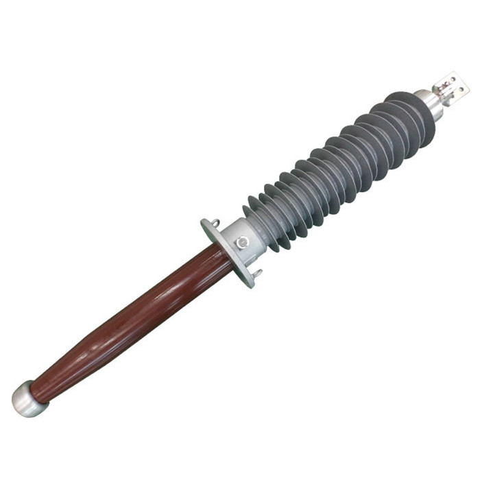
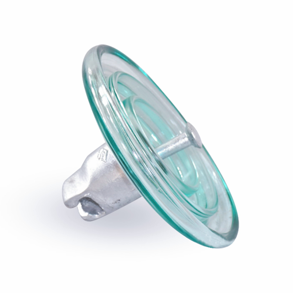
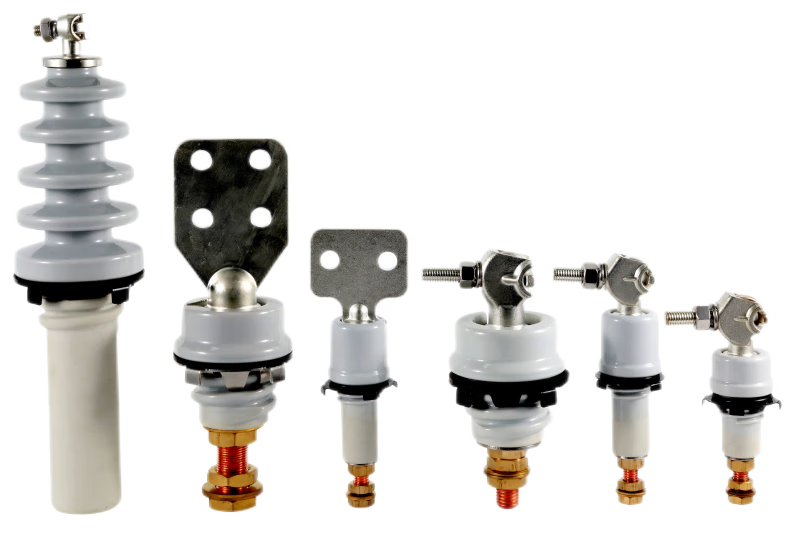
In a typical step-down pad-mounted transformer, primary bushings connect the higher-voltage supply to the primary winding, while secondary bushings connect the lower-voltage winding to the load. The main differences are their voltage ratings, current-carrying requirements and connection interfaces. Primary and secondary describe the circuit connections; live-front and dead-front describe the connection construction.
Primary bushings provide insulated connections between the incoming supply and the transformer’s primary winding. In a step-down transformer, they must withstand a higher voltage than the secondary bushings.
The primary connection may use live-front terminals or dead-front separable connectors, depending on the transformer design. The bushing’s insulation level, current rating and cable interface must match the specified equipment and application.
Transformer secondary bushings connect the secondary winding to the outgoing load cables. In a typical step-down application, this side operates at a lower voltage but carries a higher current.
For approximately the same power transferred through the transformer, lower voltage generally means higher current. Secondary bushings must therefore provide sufficient current-carrying capacity. Their terminals may also need to accommodate multiple cables per phase, depending on the transformer rating and connection arrangement.
| Comparison | Primary Bushings | Secondary Bushings |
|---|---|---|
| Connection | Incoming supply and primary winding | Secondary winding and outgoing load |
| Voltage in a step-down transformer | Higher voltage | Lower voltage |
| Current at comparable power | Usually lower current | Usually higher current |
| Connection arrangement | Live-front terminals or dead-front connectors | Terminals or connection pads suited to the load cables |
| Selection priorities | Insulation level, current rating and cable interface | Current rating, terminal dimensions and cable connections |
In many three-phase pad-mounted transformers, the primary bushings are in the left-hand compartment and the secondary bushings are in the right-hand compartment when viewed from the front. A metal barrier separates the compartments. Confirm the actual arrangement using the manufacturer’s drawing and equipment labels.

With a live-front connection, energized conductive parts are exposed within the compartment. A properly assembled dead-front connection uses insulation and shielding to enclose the energized connection. Insulating materials may include epoxy and EPDM rubber, depending on the component.
Dead-front connections are common on the primary side of pad-mounted transformers, although live-front designs are also available. Enclosing the energized connection limits exposure during normal assembled operation. It does not remove the need for qualified personnel and the equipment’s specified electrical safety procedures.
For example, manufacturer documentation lists 200 A loadbreak and 600 A deadbreak bushing options. These are different interface types, and their operating capabilities should not be inferred from the current rating alone.
A standard elbow connector generally terminates an individual cable. Secondary connections often require a different terminal arrangement to accommodate higher load currents and multiple cables per phase. The connection design should therefore be checked separately from whether the bushing serves the primary or secondary winding.
When selecting or replacing a bushing, confirm its voltage rating, insulation level, current rating and connection interface. Also check the mounting dimensions, terminal arrangement, clearances and number of cable connections. Primary and secondary bushings should not be treated as interchangeable components.
NJREC supplies transformer bushings and supports product selection based on the required specifications. For technical clarification, provide the transformer ratings, bushing drawing, connection details, quantity and applicable project standard.
The correct choice depends on both the electrical duty and the mechanical connection. Identify which winding the bushing serves, then verify its ratings and interface against the transformer documentation. You can contact NJREC for bushing selection and quotation with your project requirements.