
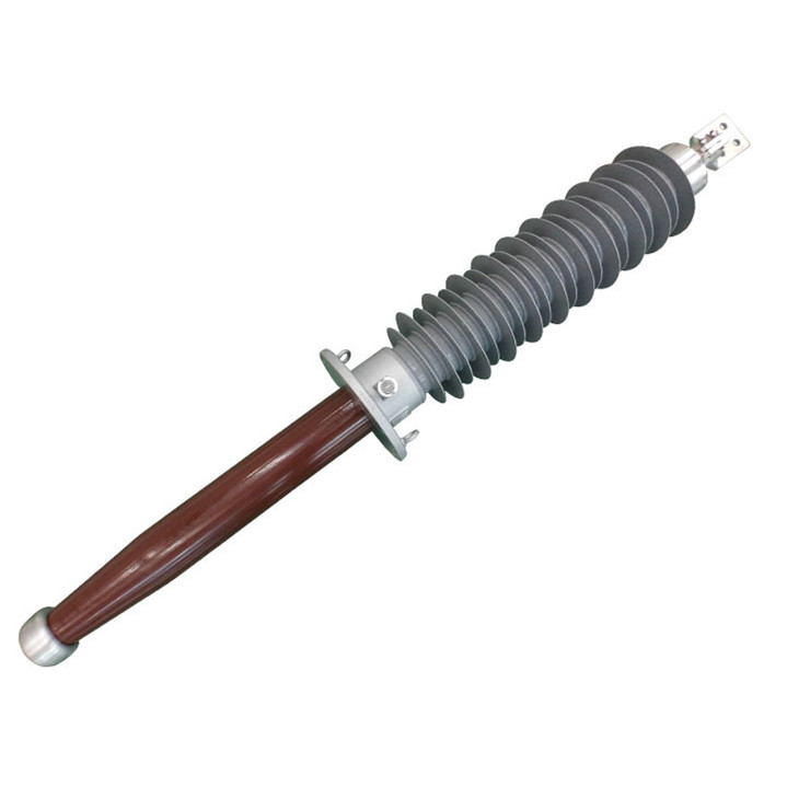

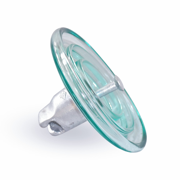
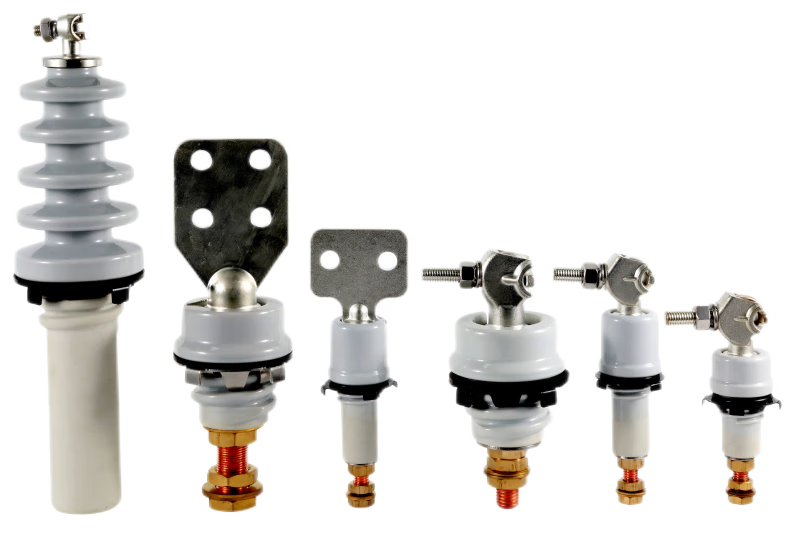
A condenser bushing allows electricity to pass through a transformer’s metal tank without making the tank itself live. Inside the bushing, a central conductor carries the current, while insulation keeps it separate from the tank. Thin metal layers within the insulation help divide the voltage into smaller steps, reducing electrical stress in areas where it would otherwise concentrate. This voltage-sharing design is why it is called a condenser bushing, or capacitive bushing.
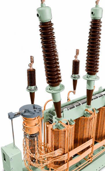
What Is Inside a Condenser Bushing?
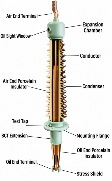
A condenser bushing contains several components with different electrical and mechanical roles. Understanding them makes the grading principle easier to follow.
- Central conductor: The current-carrying rod, tube, or conductor arrangement provides the electrical connection through the bushing.
- Main insulation: Insulating material surrounds the central conductor and separates it from the grounded mounting structure.
- Conductive grading layers: Thin conductive inserts, commonly aluminum foils, sit at designed positions within the insulation.
- External insulation: Porcelain or a composite insulating housing provides the external insulating surface. Outdoor sheds increase the surface path between energized and grounded parts.
- Mounting flange: The flange secures the bushing to the equipment and is normally connected to earth potential.
The insulation and embedded grading layers together form the condenser core. This core is different from the visible external insulator. The outer sheds do not create the internal capacitive grading.
Depending on the design, additional components include a test tap, seals, terminal fittings, and shields. Oil-filled designs may also include an oil-level indicator and an expansion space; these are not universal features of every condenser bushing.
How Does Capacitive Grading Work?
Capacitive grading controls how voltage is distributed between the energized conductor and the grounded flange. Without suitable field control, electrical stress can concentrate in particular regions, including near the grounded mounting structure. Simply adding insulation does not explain or replace the role of a carefully designed grading system.
Conductive Layers Form Capacitive Sections
Two neighboring conductive layers, separated by insulating material, form a capacitor. In a conventional condenser core, these layers are arranged concentrically around the central conductor. Together, the sections behave approximately like capacitors connected in series between high potential and earth potential.
These are not separate packaged capacitors installed inside the bushing. The capacitive structure is created by the geometry of the conductive inserts and the insulation between them.
Consider a simplified example: five equal capacitors connected in series across 250 V. Each capacitor supports 50 V. The example illustrates how a total voltage can be divided into smaller steps rather than appearing across a single insulation section.
In an actual bushing, the voltage across each section depends on its capacitance. Designers control this through the dimensions, spacing, and arrangement of the grading layers, together with the insulation properties. Equal voltage steps are a useful teaching model, not a claim that every real design has identical sections.
Controlling Radial and Axial Electric Fields
Radial field control concerns the direction outward from the central conductor toward the surrounding layers and grounded flange. Axial field control concerns the direction along the length of the bushing.
The conductive layers have carefully selected lengths and positions. Their arrangement helps manage both field directions, including electrical stress near their ends. A well-designed core distributes stress more effectively, allowing the insulation to be used efficiently. It does not make the electric field identical everywhere or eliminate the need for adequate insulation thickness and external clearances.
Why Don’t the Metal Foils Cause a Short Circuit?
The metal foils do not form a continuous conducting bridge from the central conductor to earth. Insulating material separates neighboring layers, preventing direct metallic contact between them.
Intermediate grading layers are generally electrically floating: they are not all wired together or directly grounded. Under alternating voltage, capacitive coupling establishes their potentials. Connections at the inner and outer boundaries depend on the specific design, including its test-tap arrangement.
The load current travels along the main conductor. A much smaller capacitive current is associated with the insulation system under AC voltage. These are different paths and functions. The foils shape the electric field; they do not carry the transformer's load current successively through the insulation.
OIP and RIP: Different Materials, Similar Grading Principles
OIP and RIP describe the main insulation technology. Both can use conductive layers to produce a capacitance-graded condenser core.
In OIP condenser bushings, the paper insulation is dried and impregnated with insulating oil. The oil and paper together provide the dielectric insulation between grading layers.
In RIP condenser bushings, the paper core is impregnated with a curable resin, producing solid main insulation. RIS uses a synthetic material instead of paper in a resin-impregnated core.
These material differences do not change the fundamental purpose of capacitive grading. They also do not identify the external housing: core insulation and external insulation are separate design choices. A dry condenser core can still operate with its lower end immersed in transformer oil.
Frequently Asked Questions
Do all transformer bushings have a condenser core?
No. Non-condenser bushings also exist. Their main insulation does not contain the intentional capacitive grading layers described here. Whether a bushing uses a condenser core depends on its electrical duties and design requirements, rather than simply whether its exterior looks like porcelain.
Does a condenser bushing correct the transformer’s power factor?
No. Its capacitance is primarily used to control electric-field distribution within the insulation system. It is not a power-factor-correction capacitor bank. Although capacitive current flows under AC voltage, that does not make reactive-power compensation the bushing's intended function.
Does oil-to-air mean the same thing as OIP?
No. Oil-to-air describes the media surrounding the two ends of the bushing. OIP describes oil-impregnated paper inside its main insulation. An oil-to-air bushing can therefore use another suitable core technology, such as RIP. Application interface and core insulation should be identified separately when describing a product.
Understanding the condenser core explains how the bushing manages electrical stress. Actual product performance also requires verification: IEC 60137 specifies characteristics and tests for insulated bushings within its scope. For a particular installation, the selected design, ratings, interfaces, and supporting test documentation must match the equipment requirements.