

Introduction: A transformer bushing retrofit succeeds when the replacement matches both the electrical duty and the existing mechanical interface.
Replacing a transformer bushing requires more than matching voltage and current. The connector, mounting geometry, length, orientation, and available installation space must correspond to the existing equipment. A replacement high-voltage ANSI bushing can have suitable electrical characteristics while creating installation problems at the conductor termination, flange, bolt pattern, thread, or enclosure opening. Retrofit purchasing should begin with evidence from the old bushing and its installation position. The practical path is to document the interface, identify possible connector forms, review electrical requirements separately from mechanical fit, and submit the information for model-specific drawing review. NJREC lists several connector and structural options for ANSI transformer bushings, while the correct configuration depends on the existing equipment and approved engineering information.
A transformer bushing performs an electrical insulation function and a mechanical installation function at the same time. The electrical review covers rated voltage, rated current, insulation level, and dielectric-test requirements. IEC 60076-5 provides relevant background for transformer insulation and dielectric-test considerations. The mechanical review answers a different set of questions: How does the conductor terminate? How is the bushing retained? Where does the flange sit? Which holes or threads are used? How far does the bushing extend into the transformer or enclosure? These questions form a connected risk chain. A replacement using a terminal post where the existing conductor attaches through an eyebolt can require a different lug, connection direction, and tightening method. A spade connector can vary in hole size, hole count, spacing, and contact width. A sidewall-threaded arrangement depends on the mating thread and engagement. A change in flange position or overall length can affect sealing, conductor reach, internal clearance, and tool access even when the main porcelain body appears similar. During a planned outage, the transformer nameplate identifies the equipment but may not contain every interface dimension of the installed bushing. Useful retrofit evidence includes the old bushing drawing, nameplate information, clear photographs, connector measurements, flange details, and views of the installation position. If the original drawing is unavailable, carefully measured site information can support an initial technical review. Photographs should include the complete terminal, nearby hardware, mounting surface, cable or bus routing, and available tool access. The surrounding installation is part of the fit decision. A bushing may pass through a transformer tank, cover, cabinet, or grounded structure, and the connection direction must leave room for the conductor and tools. Nearby energized equipment can also affect inspection and replacement work. HSE electricity guidance emphasizes competent personnel and controlled procedures for electrical work, while HSE GS6 provides general awareness of electrical distances around high-voltage equipment. Site safety procedures and approved engineering information determine the actual work method.
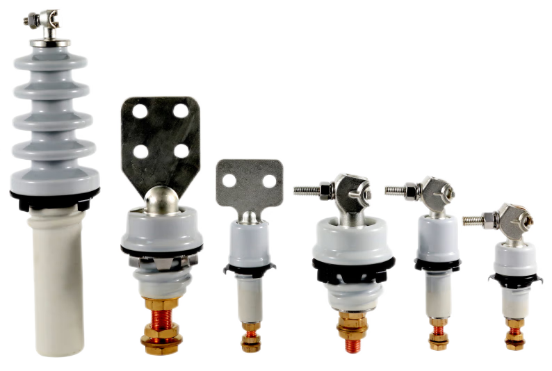
The connector form determines how the transformer conductor reaches the bushing and how the connection is secured. It influences the current path, tightening method, conductor alignment, installation access, and space required around the terminal. NJREC lists eyebolt, spade connector, sidewall threaded, and terminal post forms among the connector options associated with its ANSI transformer bushing range. The product information also includes multiple spade-hole and size forms. These details are useful starting points for an interface discussion; the old-part evidence establishes which candidate configuration deserves review.
A spade connector can suit a flat contact arrangement with bolted attachment, but its shape alone cannot determine the retrofit fit. Hole count, hole diameter, center-to-center spacing, metal thickness, contact width, and conductor approach all affect assembly. NJREC lists one-hole, two-hole, four-hole, six-hole, and eight-hole spade variations, along with different size references. This range makes accurate documentation of the installed part important. Record whether the conductor is a flexible lead, rigid bus, cable lug, or another arrangement. Measure the hole pattern and note the direction from which the conductor approaches the bushing. A replacement spade with the same number of holes may still create a poor assembly if the contact centerline shifts, the conductor reaches the tank wall, or the tightening tool cannot be positioned correctly. Photographs should show the terminal, fasteners, conductor, surrounding structure, and access space rather than only the front face.
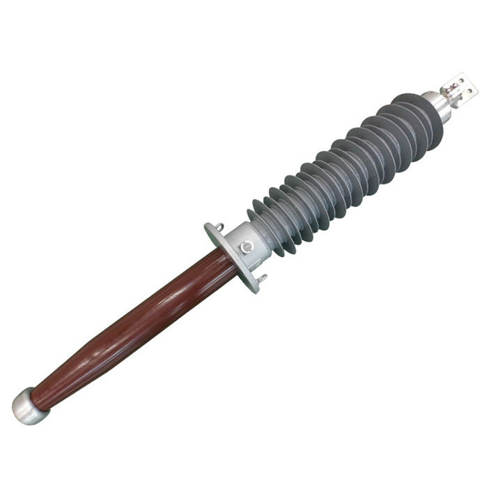
Sidewall-threaded and terminal-post arrangements change how the connection is retained and accessed. A threaded connection depends on thread type, diameter, pitch, engagement length, shoulder position, and the mating component. A terminal post depends on diameter, height, attachment method, conductor lug, and clearance above the mounting surface. These details influence both mechanical retention and the conductive path. An eyebolt creates another arrangement in which eye size, bolt specification, conductor position, and tightening access must correspond to the existing installation. A search for an “ANSI transformer bushing with eyebolt” becomes more useful when supported by measured interface data rather than visual similarity. A supplier drawing should identify the proposed connector and show the relevant hole, thread, terminal, and conductor dimensions. The product range also mentions cylindrical, tapered, and straight-tube structures, so the body shape and mounting arrangement should be included in the same review.
Mounting geometry determines whether the bushing can sit in the existing opening and connect correctly after installation. Compare the old bushing and proposed drawing as complete assemblies. Relevant information includes flange diameter, bolt-circle or hole spacing, hole diameter, fastener arrangement, flange thickness, body diameter, terminal position, thread details, overall length, and the lengths above and below the mounting surface. The flange must meet the mounting surface in the intended position, while the assembly must provide the required sealing and retention arrangement for the equipment design. Overall and integrated length deserve particular attention where internal space is limited. The internal projection must reach its intended conductor position without approaching windings, shields, tank components, or other internal structures. The external projection must also leave room around enclosure panels, barriers, adjacent conductors, and maintenance tools. NJREC describes integrated lengths reaching up to 2800 mm, which is a maximum description for applicable configurations rather than a standard length for every model. Installation direction can change cable routing, conductor stress, access, and clearance even when the body diameter appears suitable. A bushing pointing upward, downward, or at an angle may require a different external connection layout. A marked-up sketch can add useful context by showing the mounting surface, connector centerline, nearby equipment, access direction, and removal path. Photographs help reveal orientation, corrosion, cable routing, and obstructions, but they rarely provide reliable scale for critical dimensions. The approval sequence should keep electrical and mechanical reviews distinct. First compare the proposed voltage, current, insulation level, and dielectric-test requirements with the project documentation. Then compare the connector, flange, holes, threads, length, orientation, and clearances with the existing installation. IEC 60076-5 can support the electrical background, while the supplier drawing and site-approved engineering information govern the interface decision. For a technical inquiry, provide the old bushing nameplate, front and rear photographs, existing drawing, connector measurements, flange and hole details, installation direction, available clearance, transformer application, quantity, and project timing. NJREC provides Request Quote and contact routes for product discussions. The requested model, connector configuration, exact dimensions, technical documents, price, delivery terms, MOQ, and lead time is worth checking for the specific project. This drawing-based approach gives engineers and equipment buyers a practical basis for deciding whether a candidate replacement merits further review.
A successful transformer bushing retrofit depends on matching the existing interface as carefully as matching the electrical requirements. Eyebolt, spade connector, sidewall threaded, and terminal post forms create different requirements for conductor arrangement, retention, access, and clearance. Flange geometry, hole spacing, thread engagement, overall length, integrated length, and installation direction complete the fit review. Before requesting a final quotation, gather the old bushing drawing, photographs, nameplate data, measurements, and installation-space information. Submit those details to NJREC for model-specific drawing review, then confirm the configuration, technical documents, commercial terms, and project timing.
A:NJREC lists eyebolt, spade connector, sidewall threaded, and terminal post forms. The product information also shows multiple spade-hole and size forms, including one-hole, two-hole, four-hole, six-hole, and eight-hole variations. The applicable connector depends on the requested model and the existing installation details.
A:Provide the old connector type, hole count and diameter, hole spacing, thread diameter and pitch where applicable, terminal dimensions, conductor arrangement, flange details, mounting direction, overall length, integrated length, and surrounding clearance. The old bushing drawing, nameplate, photographs, and a marked-up installation sketch give the supplier a practical basis for model-specific review.
A:A spade connector must match the existing hole pattern, hole size, conductor arrangement, contact position, mounting geometry, and tightening space. NJREC lists multiple spade-hole and size forms, so the existing connector drawing or measured interface should accompany a request for a replacement transformer bushing with a spade connector.
Avoiding danger from overhead power lines - HSE